NYCT has integrated the following Diagnostic Systems:
Traction Motor Diagnostic System
The New York City Transit Authority (NYCTA), the largest transit authority in the U.S., integrated a Traction Motor Diagnostic System (TMDS) in October of 1998. Since then TMDS has proven to be an invaluable tool for NYCTA. Not only have NYCTA engineers been able to ensure that only reliable motors are placed in service, they have also been able to evaluate individual motor components, perfect assembly methods and qualify outside suppliers. For a complete description of the operation of a TMDS refer the TMDS Section.
The NYCTA motor shop is located in Brooklyn, New York and provides motors for the entire transit system.
Type: Fully automated, DC motor test capability only
Dynamometer: Eddy-current, water cooled, 175 horsepower
Armature power supply: 0-500 volt, 500 amp
Field power supply: 0-50 volt, 500 amp
If you would like to review the entire specification, request this specification using the document request form.
American Railway Technologies designed, built, delivered and installed the system shown below.
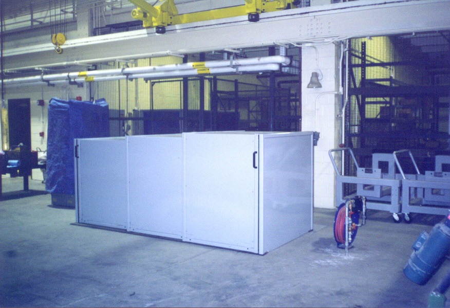
The control section, which contains the computer, monitor, keyboard, dynamometer controller and printer, is located in the vicinity of the test frame. There is no test cell in this application and therefore, a telescopic motor cover is employed. All control lines from the control cabinet are located in conduit located under the floor, which has resulted in a very clean installation.
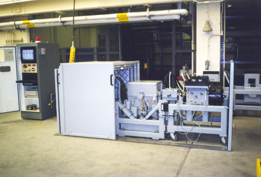
The motor cover is mounted on rollers and guided by a track system for ease of opening and closing. Note the sound deadening material on interior of the cover. In addition, this system is designed to accommodate and test two motors. By placing the dynamometer in the center of the test frame, motors are able to be mounted at both ends of the test frame. This test frame is designed specifically to accommodate Westinghouse and GE traction motors.


In order to cool the dynamometer, the air-to-water heat exchanger, has been mounted on the roof of the motor shop. A high pressure pump, located on the shop floor, then circulates the coolant. Finally an additional water-to-water heat exchanger, for cooling during hot weather, is located in a utility room along with the coolant filter.


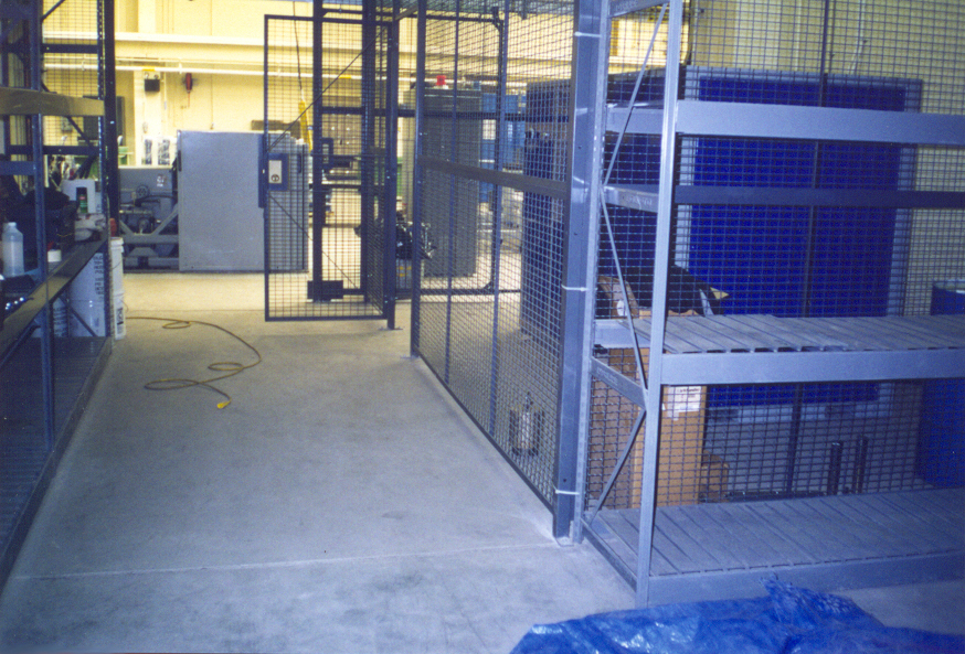
The regulator section is located in a seperate location in order to save floor space. The regulator section provides the electric power to run the motors through power cables running from the regulator to the the test area via a conduit located under the floor. You can see the regulater below, located inside the cage on the right.
The regulator section contains transformers, rectifiers, contactors and all controls necessary to power DC traction motors.